[v.1.0] (01/20/2023): Post started!
Computer Memory & Storage
- Storage
- HDD (hard disk drive): it works by spinning magnetics disk.
- SSD (solid state drive): it uses NAND-based flash memory, providing fast data access, reduces power consumption, and increases durability. It is more expensive.
- USB Drive: is a small plug-and-play device for convenient data transfer between computers.
- SD Card is commonly found in camera and smartphone. There is SD Card, Mini Card, and Micro Card.
- Memory
- RAM (random access memory): is a type of memory that store data temperarily while the computer is running. It’s fast and flexible. However, all the data is lost after the power is off.
- SRAM (static random access memory): is a fast and expensive DRAM used in high speed application like CPU caches, where quick access time is crucial.
- DRAM (dynamic random access memory): is slower and cheaper than SRAM. It needs to be constantly refreshed to maintain data.
- SDRAM
- DDR SDRAM: with examples like DDR4, DDR5.
- GGDDR SDRAM: is a specialized of DRAM with faster data transfer rates for parallel processing.
- ROM (read only memory): is a type of memory that retains data, even when the memory is off. It is used to store essential information like firmware and BIOS.
- Firmware: is a type of software stored in ROM that determines how hardware devices communicate with each others
- BIOS (basic input-output systems): first run when you booth up the computer. It is responsible for starting your computer, initializes hardware components, and hands over controls to the OS.
- RAM (random access memory): is a type of memory that store data temperarily while the computer is running. It’s fast and flexible. However, all the data is lost after the power is off.
Domain Name System (DNS)
It is the backbone of the internet.
But how does it work?
DNS is a directory: it translates human-readable domain names (i.e, www.google.com) to machine-readable IP-addresses.
There are different DNS servers with different purposes. The DNS Resolver can be provided by Cloudflare (1.1.1.1) or Google (8.8.8.8).
How does the DNS Resolver find the authoritative nameservers?
There are 3 levels of DNS:
- Root Nameservers: stores the IP-addresses of the TLD nameservers. There are 13 logical Root Nameservers. Ex: .com, .org, .edu
- Top Level Domain (TLD) Nameservers: stores the IP-addresses of the Authoritative Nameservers. Ex: google.com, wikipedia.org, mit.edu.
- Authoritative Nameservers: stores authoritative answers to queries
Such design above make DNS decentralized and robust.
How does the workflow look like?
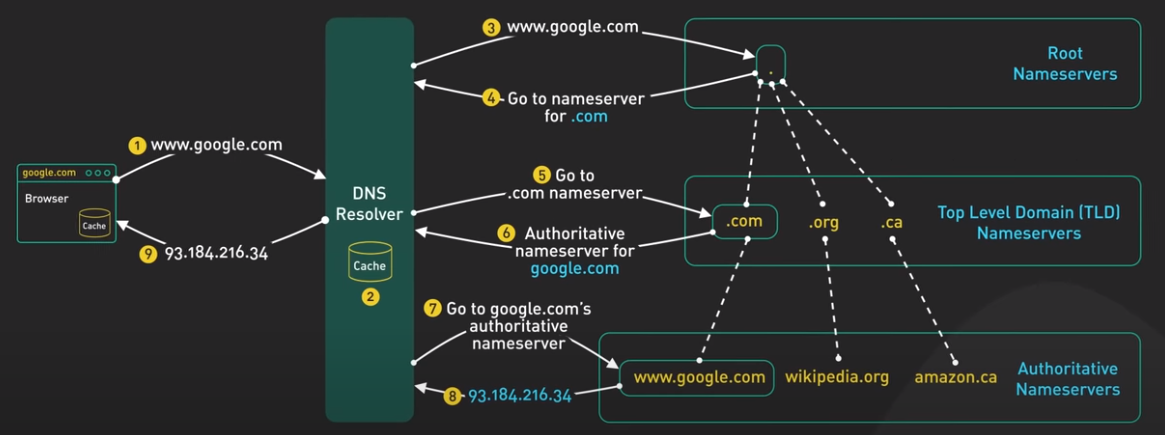
- The user types “google.com” to browser.
- The browser first checks its cache, if there is no answer, it makes the OS call to get the answer.
- The OS then reachs out to DNS Resolver.
- The DNS Resolver first checks its cache, if it is not there or if the answer is expired, it will ask the Root Nameservers.
- The Rootname Servers responses with the root name TLD Nameservers. Here, if the RootName Servers found the root name TLD Nameservers (i.e. .com as it is common) in its cache, it will return.
- The DNS Resolver then reachout to the TLD Nameservers, which return the Authoritative Nameservers for “google.com”.
- The DNS Resolver then reachout to the Authoritative Nameservers and get the IP-address of “google.com”.
- The DNS Resolver then returns the address of the IP system to the OS, and the OS returns it to the browswer.
Common Latency Numbers
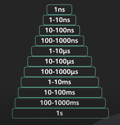
- 1 ns: Accessing CPU registers, CPU clock cycle.
- 1-10 ns: L1/L2 cache, Branch mispredict.
- 10-100 ns: L3 cache.
- 100-1000 ns: System call, MD5 hash.
- 1-10 µs: Context switches between threads.
- 10-100 µs: Higher level operations such as process a http request, sequential read, read a 8K page.
- 100-1000 µs: SSD write latency, intra-zone networking round trip, memcache/redis get operation.
- 1-10 ms: Intra-zone network latency, seek time of HDD.
- 10-100 ms: Network round-trip from US West-East.
- 100-1000 ms: Bcrypt a password, TLS handshake, reading sequentially 1GB of SSD.
- 1 s: Tranfer 1GB over the network within the same cloud region.
REST API
Representational State Transfer Application Programming Interface (REST API) is the most popular communication standard between computers over Internet. API is a way for two computers to talk to each other. The common API used by mobile and web applications to talk to the servers is called REST. For instance, Twilio, Stripe, Google Maps use REST API.
REST is not a specification, it is a loose set of rules for building web API since the early 2000s. Those rules are:
- Uniform Interface.
- Client-Server.
- Stateless.
- Cacheable.
- Layered System.
- Code on Demand (Optional).
Basics of REST API
The REST API organizes resources into a set of unique Uniform Resource Identifiers (URIs). The URIs differentiate types of resources on a server.
https://example.com/api/v3/products
https://example.com/api/v3/users
A client connects to resources by making a request to the endpoint for the resource over HTTP. The request has a specific format such as POST/products HTTP/1.1.
Here are the operations (CRUD)
POST:CREATEa new resource.GET:READthe data about an existing resource.PUT:UPDATEan existing resource.DELETE:DELETEan existing resource.
In the body of these request, there could be an optional HTTP request body that contains a custom payload of data, usually encoded in JSON.
POST/produccts HTTP/1.1
Accept: application/json

JSON: {
  "customer": "Minh Nguyen",
  "quantity": 1,
  "price": 19.00
}
The server receives a request, processes it and form the result into response.
HTTP/1.1 200 OK
Some HTTP status codes:
200: Request is successful.400: Something is wrong with our request, such as wrong syntax.500: Something is wrong at the server level, such as the server is not available.
Stateless
A REST implementation should be stateless. This means that the two parties don’t need to store any information about each other, and every request and response (cycle) is independent from all others. This attribute leads to the web application that is easy to scale and well behaved.
Pagination
If the return endpoint returns a huge amount of data, we should use pagination. A common scheme uses limit and offset as parameters. If they are not specified, the server should assume sensible default values.
/products?limit=25&offset=50
Versioning
Versioning allows an implementation to provide backward compatibility, so that if we introduce breaking changes from one version to another, consumers can get enough time to move to the next version.
There are many ways to versioning an API. The most common way is to prefix the version before the resource on the URI.
/v1/products
/v2/products
RESTful API is sensible if used correctly as it is simple and good enough, and that’s why it is so widely used. Other options are GraphQL and gRPC.
10 Key Data Structures in System Design
The choice of correct data structures based on the specification and constraints of the projects is important. To refresh the fundamentals of these data structures, please visit https://neetcode.io/.
Linked List
Linked list (or list) is a versatile and essential data structure in software development. It is great for storing and manipulating ordered data. They are useful in various applications such as task-management, social media feeds, and shopping carts.
For task-management application, a list can be used to store and organize tasks for each user. Tasks can be added, removed, or reordered easily, and users can mark them as complete or incomplete.
In social media application, e.g. Twitter (X), where they can store and display a users’ feeds in real-time, ensuring the order is correct in real-time.
Array
Array provdes a fixed-size, ordered collection of elements. They are suitable for situation where the size of the collections is known or isn’t changed frequently. Arrays are commonly used in mathematical operations, storing large datasets, or when there is a need for random access to elements.
For instance, in the weather application, an array can store temperature readings for a specific location over a defined period. This allows for easy calculations like average temperature or trends analysis.
Arrays are also used in image-processing, where each pixel’s color data can be represented in a 2D array. It enables efficient manipulation and transformation of the image.
Stack
Stacks follow the LIFO principle, and they are perfect for supporting undo/redo operations in text editors or maintaining browsing history in web browsers.
In the text editors, a stack can be used to store each change made to the text, making it simple to revert to a previous state when the user triggers an undo operation.
Queue
Queues operate on the FIFO principle, and they are good for managing printer jobs, sending actions in games, or handling messages in chat applications. Specifically, in chat applications, a queue can be used to store incoming messages in the order they are received. It ensures that they are displayed to the recipient in the correct sequence.
Heap
Heaps are used for task scheduling and memory management. They are helpful in implementing priority queues where we need to access the highest or lowest priority item efficiently.
Tree
Trees organize data hierarchically. They are useful for representing data with natural hierarchies or relationships. Trees are used in database indexing, file systems, or AI decision tree.
For database indexing, tree helps speed up search, insert, or delete operations. For example, B-trees and B+ trees are commonly used in relational databases to efficiently manage and index large amount of data.
Hash Table
Hash table (or hashmap) allows for efficent data lookup, insertion, and deletion. They use a hash function to map keys to their corresponding storage locations. It enables constant-time access to the stored values. Hash tables are widely used in various applications, such as search engines, caching systems, and programming language interpreters or compilers.
In search engine, hash table allows to store and quickly retrieve indexed data based on keywords. This provides fast and relevant search results.
Caching systems may use hash tables to store and manage cached data. It allows for eapid access to frequently requested resources and improves overall system performance.
Suffix Tree
Suffix trees (or tries) are specialized for searching strings in documents. This makes them perfect for text editors and search algorithms. In a search engine, a suffix tree can be used to efficiently locate all occurrences of a search term within a larger corpus of text.
Graph
Graphs are all about tracking relationships or finding paths. This makes them invaluable in social networks, recommendation engines, and pathfinding algorithms.
In a social network, a graph can be used to represent a connections between users. It enables features like friend suggestion or analyzing network trends.
R-tree
R-trees are good at finding nearest neighbors. They are crucial for mapping apps and geolocation services. In a mapping applications, R-trees can be used to store spatial data, such as points of interest. This enables efficient queries to find the nearest locations based on the user’s current position.
Cache Friendliness Relations to Data Structures
CPU cache is a small, fast memory between the main memory (RAM) and the CPU. It stores recently accessed data and instructions, so the CPU can access them quickly without fetching them from the slower main memory.
Different data structures have different levels of cache friendliness based on how their elements are stored in memory. Contiguous memory storage (arrays) allows for better cache locality and fewer cache misses, resulting in improved performance. When an array element is accessed, the cache can be prefetch and store nearby elements, anticipating that they might be accessed soon. While data structures with non-contiguous memory storage (linked-list) can experience more cache misses and reduce performance. In a linked list, elements are stored in nodes scattered throughout the memory and each node contains a pointer to the next node in the sequence. This makes it difficult for the CPU to predict and load the next node before it’s needed.
Other data structures have varying degrees of cache friendliness based on their implementation and use case. This disparity in access times can lead to performance issues in modern computing, particularly in situations where cache misses occur frequently.
Cache Systems
Caching is a common technique in modern computing to system performance and reduce response time. From the front-end to back-end, caching plays a crucial role in improving the efficiency of various applications and systems.
A typical system architecture involves several layers of caching. At each layer, there are multiple strategies and mechanisms for caching data, depending on the requirements and constraints of the specific application.
Computer Caching Mechanism
The most common hardware cache are L1, L2, and L3 caches.
- L1 cache (KBs) is the smallest and fastest cache, typically integrated into the CPU itself. It stores frequently accessed data and instructions, allowing the CPU to quickly access them without having to fetch them from slower memory.
- L2 cache (MBs) is larger but slower than L1. It is typically located on the CPU die or on a separate chip.
- L3 cache is larger but slower than L2. It is typically shared between multiple CPU cores.
Another common hardware cache is the translation lookaside buffer (TLB). It stores recently used virtual-to-physical address translations. It is used by the CPU to quickly translate virtual memory addresses to physical memory addresses, reducing the time needed to access data from memory
At the OS level, there are page cache and other file system caches. Page cache is managed by the OS and resides in the main memory. It is used to store recently used disk blocks in memory. When a program requests data from the disk, the OS can quickly retrieve the data from memory instead of reading it from disk. There are other caches managed by the OS, such as inode cache. These caches are used to speed up file system operations by reducing the number of disk accesses required to access files and directories.
Cache in System Architecture
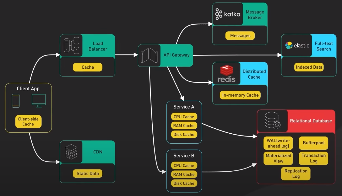
Front-end: web browsers can cache HTTP response to enable faster retrieval of data. When we request data over HTTP for the first time and it returned with an expiration policy in the HTTP header; we request thee same data again, and the broweser returns the data from its cache if available.
CDNs: are used to improve the delivery of static contents (images, videos, web assets). When a user requests a content from a CDN, the CDN network looks for the requested content in its cache. If the content is not already in the cache, the CDN fetches it from the origin server and caches it on its edge servers. When another user requests the same content, the CDN can deliever the content directly from its cache, eliminating the need to fetch it from the origin server again.
Load-balancers: implement cache resources to reduce the load on back-end servers. When a user requests content from a server behind a load balancer, the load balancer can cache the response and server it directly to future users who request the same content. This can improve response times and reduce the load on back-end servers.
Messeging infrastructure, message brokers such as Kafka can cache a massive amount of messages on disk. This allows consumers to retrieve the message at their own pace. The messages can be cached for a long period of time based onthe retention policy.
Distributed caches such as Redis can store key-value pairs in memory, providing high read/write performance compared to traditional databases.
Full-text search engines like Elastic Search can index data for document search and log search, providing quick and efficient access to specific data.
Relational database: has multiple levels of caching:
- Data is typicaly written to WAL (write-ahead-log), before indexed in a B-tree.
- Buggerpool is a memory area used to cache query results.
- Materialized-view can precompute query results for faster performance.
- Transaction-log records all transactions and updates to the database.
- Replication-log tracks the replication state in the database cluster.
Redis’s Versitality
Redis is an in-memory data structure store. It is most commonly used as a cache. It support many data structure such as strings, hashes, lists, sets, and sorted sets. Redis is known for its speed.
Cache
The number one use case for Redis is caching objects to speed up web applications. Here, Redis stores frequently requested data in memory. They allows the web servers to return frequently accessed data quickly. This reduces the load on the database and improves the response time for the application.
At scale, the cache is distributed among a cluster of Redis servers. Sharding is a common technique to distribute the cache load evenly across the cluster.
Session
Redis can be used as a session storage to share session data among stateless servers. When a user logs into a web application, a session data is stored in Redis along with a unique session ID that is returned to the client as cookie. When the user makes a request to the application, the session ID is included in the request and the stateless web server retrieves the session data from Redis using the ID.
Redis is an in-memory database. The session data stored in Redis will be lost if the Redis server restarts. Even through Redis provides persistence options like snapshots or AOF (Append-Only File) that allow session data to be saved to disk and reloaded into memory in the event of a restart, these options often take too long to load on restart to be practical.
In production, replication is usually used instead such as back-up instance. If there is a crash, the back-up instance will be promoted to take over the traffic.
Distributed Lock
Distributed locks are used when multiple nodes in an application need to coordinate access to some shared resource. Redis is used as a distributed lock with is atomic commands like SETNX (set if not exist). The command allows a caller to set a key only if it does not already exist.
For instance, client_1 tries to acquire the lock by setting a key with a unique value and a timeout using the SETNX command, SETNX lock "1234abcd" EX 3. If the key was not already set, the SETNX command returns 1, indicating that the lock has been acquired by client_1. client_1 finishes its work and releases the lock by deleting the key. If the key was already set, the SETNX command returns 0, indicating that the lock is already held by another client. In this case, client_1 waits and retries the SETNX until the lock is released by other client.
Rate Limiter
Redis can be used as a rate limiter by using its increment command on some counters and setting expiration times on those counters.
Basic rate-limiting: For each incoming request, the request IP or user ID is used as a key. The number of requests for the key is incremented using the INCR command in Redis. The current count is compared to the allowed rate limit. If the count is within the rate limit, the request is processed. If the count is over the rate limit, the request is rejected. The keys are set to expire after a specific time-window (minutes) to reset the counts for the next time window.
There is also a Leaky Bucket Algorithm implemented using Redis.
Rank/Leaderboard
For most games that are not super high scale, Redis is a way to implement various types of gaming leaderboards. Sorted Sets (or sorted container or sorted hashmap) are the fundamental data structure that enables this. Here, we can retrieve the data in O(logN).
Continuous Integration / Continuous Delivery (CI/CD)
CI/CD is a software development process including:
- Continuous Integration
- Code commit (multiple developers).
- Build.
- Unit and integration tests.
- Create application or service image.
- Continuous Delivery
- Functional testing.
- User acceptance testing.
- Configuration automation.
- Load testing.
- Deployment.
It eliminates much of the manual human intervention traditionally require to get new code to production. CI/CD promises software teams to deploy better quality software and faster.
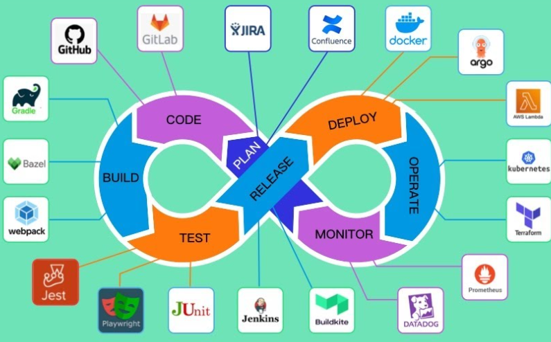
Continuous Integration: Build, Test, Release
CI is the practice of using automation to enable teams to merge code changes into the shared repository early and often. Each commit triggers an automated workflow on a CI server that runs a series of tasks to make sure the commit is safe to merge into the main branch.
A good CI process relies on a set of good tests. It is non-trivial to maintain a set of tests with sufficient coverage that is not flakey.
High test coverage usually takes longer to run. This impacts developer’s productivity.
Continuous Deployment: Deploy, Operate, Monitor
Real CD is hard as the practice is not as common as CI. Many teams only practice CD on the most basic types of systems. These systems are usually stateless such as API or web server tiers.
A very few teams has the resource to implement real continuous, hands-off deployment on complex stateful systems like database, backend clusters, or other types of stateful systems like websocket cluster.
Instead, these systems are usually on a fixed deploy cadence. The deployment process is manual, risky, and time consuming. They require the care of dedicated platform team. It is rare to see these systems deployed fully, continuously, and automatically.
Kubernetes (K8s)
Kubernetes is an open-source container orchestration platform. It automates the deployment, scaling, and management of containerized applications.
Kubernestes is a set of machines called nodes, that are used to run containerized applications. There are two core pieces in a Kubernestes cluster:
- Control plane: responsible for managing the state of the cluster. In production environment, the control plane runs on multiple nodes that span across several data center zones.
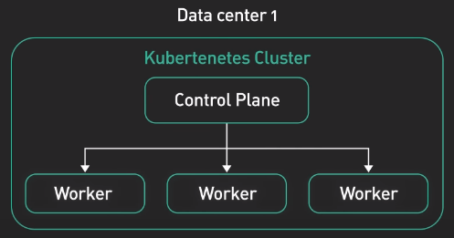
- Set of worker nodes: run the containerized application workloads. The containerized applications run in a Pod. Pods are the smallest deployable units in Kubernetes. Pods hosts one or more containers and provides shared sotrage and networking for those containers. Pods are created and managed by the Kubernetes control plane. They are the basic building blocks of Kubernetes applications
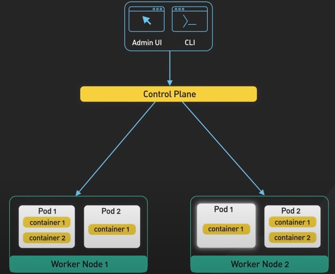
Control Plane
Control plane consists of a number of core components such as API server, controller manager, scheduler, etcd. The API server is the primary interface between the control plane and the rest of the cluster. It is used by the API server and other components of the control and retrieve information about the cluster. It exposes a RESTful API that allows clients to interact with the control plane and submit requests to manage the cluster.

Etcd
Etcd is a distributed key-value store. It stores the cluster’s persistent state.
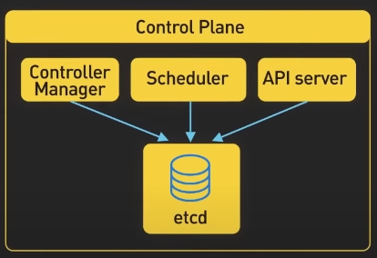
Scheduler
The scheduler is responsible for scheduling pods onto the worker nodes in the cluster. It uses the information about the resource required by the pods and available resources on the worker nodes to make the placement decisions

Controller Manager
Controller manager is responsible for running controllers that manage the state of the cluster. For instance
- The replication controller ensures that the desired number of replicas of a pod are running.
apiVersion: v1
kind: ReplicationController
metadata:
  name: nginx
spec:
  replicas: 4
- The deployment controller, which manages the rolling update and rollback of deployments.
Worker Nodes
The core compoenents of Kubernetes that run on the worker nodes include Kubelet, Container Runtime, and Kube-proxy.
- Kubelet: is a daemon that runs on each worker node. It is responsible for communicating with the control plane. It receives instructions from the control plane about which pods to run on the node and ensures that the desired state of the pods is maintained.
- Container Runtime runs the containers on the worker nodes. It is responsible for pilling the container images from a registry, starting and stopping the containers, and managing the containers’ resources.
- Kube-proxy: is a network proxy that runs on each worker node. It is responsible for routing traffic to the correct pods. It also provides load balancing for the pods and ensures that the traffic is distributed evenly across the pods
Use Cases
It’s about trade-off.
Pros:
- Kubernetes is scalable and highly available. It provides features like self-healing, automatic rollbacks, and horizontal scaling. It makes it easy to scale out applications up and down as needed, allowing us to respond to changes in demannd quickly.
- Kubernetes is portable. It helps us deploy and manage applications in a consistent and reliable way regardless of the underlying infrastructure. It runs on-premise, in a public cloud, or in a hybrid environment. it provides a uniform way to package, deploy, and manage applications.
Cons:
- Kubernetes is complex to set up and operate! The upfront cost is high, especially for organizations new to container orchestration. It requires a high level of expertise and resources to set up and manage a production Kubernetes environment.
- Kubernetes is costly. It requires a certain minimum level of resources to run in order to support all the features. Thus, it is an overkill for smaller organizations.
Services: Amazon EKS, Google Cloud GKE, or Azure AKS.
CAP Theorem
Consistency-Availability-Partition Tolerance (CAP) Theorem explains the trade-off between consistency, availability, and partition tolerance in distributed systems. The CAP theorem helps us think in a high-level trade-off to consider when there is network partition.
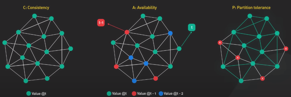
Consistency refers to the property of a system where all nodes have a consistent view of the data. It means all clients see the same data at the same time no matter which node they connect to.
Availability refers to the ability of a system to respond to requests from users at all time.
Partition Tolerance refers to the ability of a system to continue operating even if there is a network partition.
Network Partition
A network partition happens when nodes in a distributed system are unable to communicate with each other due to network failures. When this happen, a system must choose between consistency and availability.
- If the system prioritizes consistency, it may becomes unavailable until the partition is resolved.
- If the system prioritizes availability, it may allow updates to the data. This could result in data inconsistencies until the partition is resolved.
Banking System Example
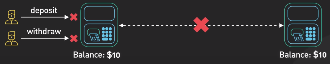
For instance, let’s say we have a tiny bank with 2 ATMs connected over a network. The ATMs support 3 operations: deposit, withdraw, and check balance. No matter what happens, the lance should never go below zero. There is no central database to keep the account balance, it is stored on both ATMs. When a customer uses an ATM, the balance is updated on both ATMs over the network. This ensures that the ATMs have a consistent view of the account balance.
If there is a network partiotion and the ATM are unable to communicate with each other, the system must choose between consistency and availability.
- If the bank prioritizes consistency, the ATM may refuse to process deposit or withdrawals until the partition is resolved. This ensures that the balance remains consistent, but the system is unavailable to customers.
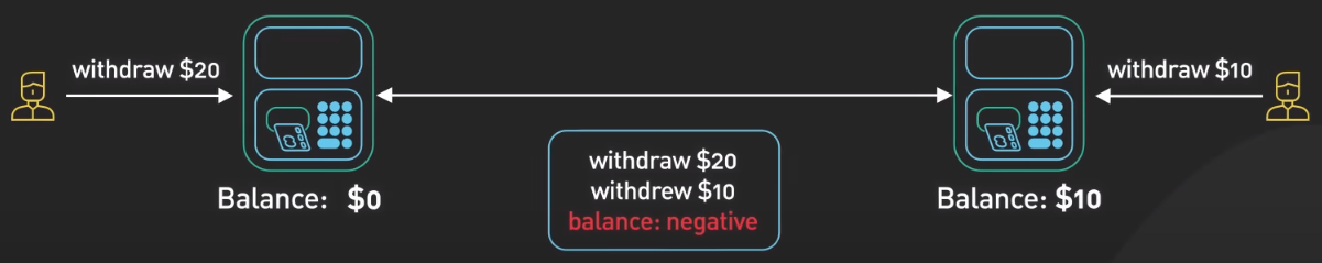
- If the bank prioritizes availability, the bank may allow deposit or withdrawals to occur but the balance may be inconsistent until the partition is resolved. When there is a network partition, the customer could withdraw the entire balance from both ATMs. When the network is back online, the inconsistency is resolve and the balance is negative, which is not good
7 Layers of OSI Model
The Open System Interconnect (OSI) model is a theoretical framework that provides one way of thinking about networking. It splits the network communication between two devices on a network into seven abstraction layers.
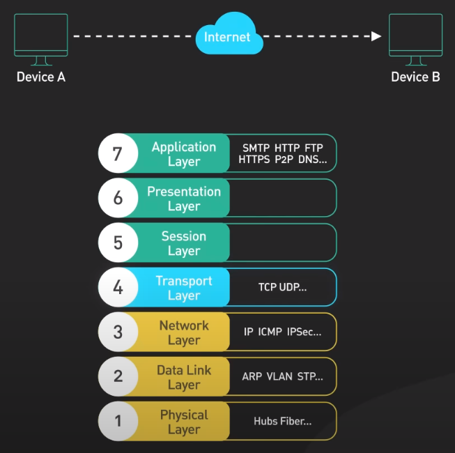
Physical Layer
The physical layer is responsible for transmitting raw bits of data across a physical connection.

Data Link Layer
The data link layer takes the raw bits from the physical layer and organizes them into frames. It ensures that the frames are delivered to the correct destination. The Ethernet primarily lives in this layer.
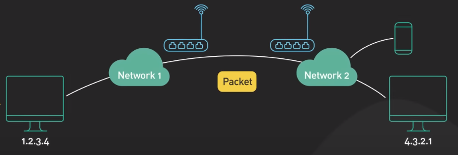
Network Layer
The network layer is responsible for routing data frames across different networks. The IP part of TCP/IP is a well-known example of this layer.
Transport Layer
The transport layer handles end-to-end communication between 2 nodes. This is the layer where the TCP and UDP protocols live.
TCP provides reliable, end-to-end communication between devices. It does this by dividing the data into small, manageable segments and sending each segment individually. Each segment has asequence number attached to it. The receiving end uses the sequence numbers to reassemble the data in the correct order.

TCP also provide error checking to make sure that the data was not corrupted during transmission.
UDP is a protocal that is similar to TCP but is simpler and faster. Unlike TCP, UDP does not provide the same level of error-checking and reliability. It simply send packets of data from one device to another. The receiving end is responsible for determining whether the packets were received correctly. If an error is detected, the receiving end simply discards the packet.
Session, Presentation, Application Layers
The analysis of these layers in OSI model is not useful in practice as the OSI is too fine-grained and does not reflect reality. Let’s consider them as application protocols like HTTP.
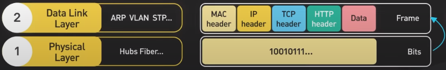
Networking Workflow

Let’s see how the data is move through the layer:
-
- When a user sends an HTTP request to a webserver over the network, the HTTP header is added to the data at the application layer.
-
- A TCP header is added to the data. It encapsulated into TCP segments at the transport layer. The header contains the source port, destination port, and sequence number.
-
- The segments are then encapsulated with an IP header at the network layer. The IP header contains the source and destination IP addresses.
-
- A MAC header is added at the data link layer, with the source and destination MAC addresses. Here, the MAC addresses are the ones of routing devices, not the computer itself in reality.
-
- The encapsulated frames are sent over the network in raw bits in the physical layer.
- 6-10. When the webserver receives the raw bits from the network, it reverses the process. The headers are removed layer-by-layer, and eventually, the webserver processes the HTTP request.
CDN
Content delivery network (CDN) should be used whenever HTTP traffic is served. Fundamentally, a CDN brings content closer to the user. This improves the performance of a web service as perceived by the user. It is noted that performance is critical to user engagement and retentionn as a 0.1-second improvement of mobile site speed increases conversion rates by 8.4% for retails sites and 10.1% for travel sites.
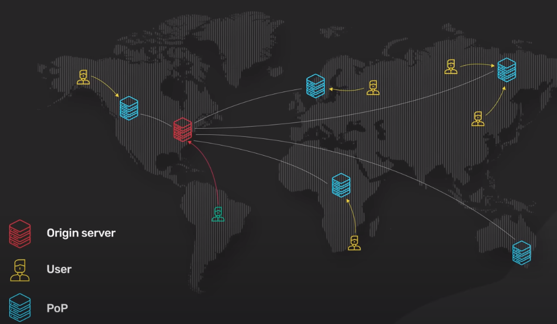
To bring the server closer to the users, CDN deploys servers at hundreds of locations all over the world. These server locations are called Point of Presence (PoP). A server inside the PoP is called edge server. Having many PoPs all over the world ensures that every user can reach a fast-edge server close to them.
Routings
Different CDNs, e.g. Amazon Cloudfront or Cloudflare, use different technologies to direct a user’s request to the closest PoP. Two common ones are DNS-based routing and Anycast.
- With DNS-based routing, each PoP has its own IP address. When the user looks up the IP address for the CDN, DNS returns the IP address of the PoP closest to them.
- With Anycast, all PoPs share the same IP address. When the request comes into the Anycast netowrk for that IP address, the network sends the request to the PoP that is closest to the requester.
Edge Server & Static Contents
Each edge server acts as a reverse proxy with a huge content cache. Static contents are cached on the edge server in this content cache. If a piece of content is in the cache, it could quickly returned to the user. Since the edge server only ask for a copy of the static content from the origin server if it is not in the cache. This greatly reduces the load and bandwidth requirements of the origin server cluster.
A modern CDN can also transform static content into more optimized formats.
Performance
The edge server also serve an important role in the modern HTTP stack: All TLS connections terminate ath the edge server. TLS handshakes are expensive. The commonly used TLS versions like TLS 1.2 take several network round trips to establish. However, terminating the TLS connection at the edge will significantly reduce the latency for the user to establish an encrypted TCP connection. This is why modern sites send dynamic uncacheable HTTP content over the CDN (single-page website).
Security
All modern CDNs have huge network capacity at the edge. This is the key to provide effective DDoS protection against large-scale attacks by having the network with a capacity much larger than the attackers.
Availability
The modern CDN improves availability as by nature, a CDN is higly distributed. By having copies of contents available in many PoPs, a CDN can withstand many more hardware failures than the origin servers.
gRPC
gRPC is an open-source remote procedure call framework created by Google in 2016. It’s a rewritten software of Google’s internal Remote Procedure Call (RPC).
RPC is a function call within a process to execute some code. A remote procedure call enables one machine to invoke some code on another machine as if it is a local function call from a user’s perspective.
gRPC is a popular implementation of RPC. Many organizations have adopted gRPC as the preferred RPC mechanism to connect a large number of microservices running within and across data centers.
Why gRPC so popular?
- gRPC has a large ecosystem for all languages. It’s very easy to produce production ready and type-safe APIs that scale well. The core of this ecosystem is the use of Protocol Buffers as its data interchange format. Protocol Buffers is a language-agnostic nad platform-agnostic mechanism for encoding structured data. gRPC uses Protocol Buffers to encode and send data over the wire by default.
- While gRPC could support other encoding formats like JSON, Protocol Buffers provide several advantages that make it the encoding format of choice for gRPC.
- Protocol Buffers support strongly-typed schema definitions. The structure of the ata over the wire is defined in a proto file. Protocol Buffers provide broad tooling support to turn the schema defined in the proto file into data access classes for all popular programming languages.
- A gRPC service is also defined in a proto file by specifying RPC method parameters and return types.
- The same tooling is used to generate gRPC client and server code from the proto file. Developers use these generated classes in the client to make RPC calls and in the server to fulfill the RPC requests.
- By supporting many programming languages, the client and server can independently choose the programming language and ecosystem best suited for their own particular use cases. This is not common for most other RPC frameworks.
- gRPC is also known for its high-performance out of the box with 2 factors.
- First, Protocol Buffers is a very efficient binary encoding format. This is much faster than JSON.
- Second, gRPC is built on top of HTTP/2 to provide a high-performance foundation at scale. The use of HTTP/2 brings many benefits (multiplexing, stream prioritization, binary protocol, server push). gRPC uses HTTP/2 streams which allows multiple streams of messages over a single long-lived TCP connection. This allows the gRPC framework to handle many concurrent RPC calls over a small number of TCP connections between clients and servers.
Workflow
Let’s walk through a flow from a gRPC client to a gRPC server.
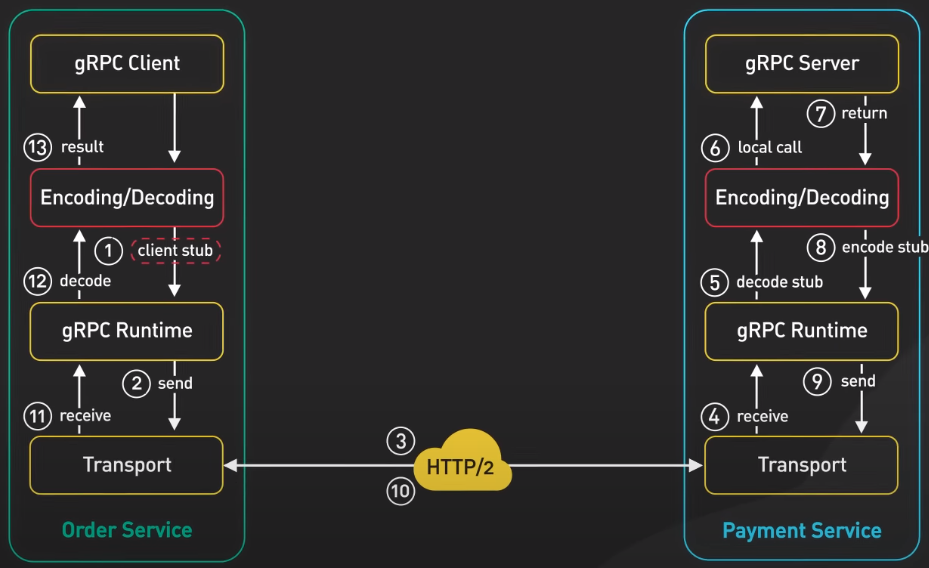
-
- When the Order Service make a gRPC call the the Payment Service, it invokes the client code generated by gRPC tooling at build time. This generated client code is called a client stub.
-
- gRPC encodes the data passed to the client stub into Protocol Buffers and sends it to the low-level transport layer.
-
- gRPC sends the data over the network as a stream of HTTP/2 data frames. Due to binary encoding and network optimization, gRPC is said to be 5 times fasters than JSON.
- 4-6. The Payment Service receives the packets from the network, decodes them, and invokes the server application.
- 7-9. The result returned from the server application gets encoded into Protocol Buffers and sent to the transport layer.
- 10-13. The Order Service receives the packets, decodes them, and sends the result to the client application.
Use Case
gRPC is known to be the inter-service communication mechanism of choice between microservices in the data centers. Its broad support for many programming languages allows services to choose their own language and developer ecosystems best suited for their own use cases.
GraphQL
GraphQL is a query language for API developed by Meta. It provides a schema of the data in the API and gives clients the power to ask for exactly what they need. GraphQL sits between the client and the backend services. It could aggregate multiple resource requests into a single query. It also supports mutations and subscriptions.
Mutations are GraphQL’s way of applying data modifications to resources.
Subscriptions are GraphQL’s way for clients to receive notifications on data modifications.
GraphQL vs. REST: Similarity
In practice, both GraphQL and REST send HTTP requests and receive HTTP responses.

Let’s look at a REST operation
# rest
https://example.com/api/v3/products
https://example.com/api/v3/user
REST centers around resources, and each resource is identified by an URL. To fetch a book from a bookstore API, it could look something like this
{
    "title": "Harry Porter",
    "authors": [
        {
            "name": "J.K.Rowling"
        },
    ...
    ]
}
The end point will be GET /book/123.
Let’s look at a REST operation
# graphql query
type Query {
    book(id: ID!): Book
}
Here’s what data transfer looks like for GraphQL
type Book {
    id: ID
    title: String
    authors: [Author]
}

type Author {
    id: ID
    name: String
    books: [Book]
}
The end point will be GET /graphql?query={ book(id: "123") {title, authors {name}}}.
As we can see, both REST and GraphQL make a request via an URL and both can return a JSON response in the same shape.
GraphQL vs. REST: Difference
With GraphQL, we specify the exact resources we want and also which fields we want. While in REST, the API implementer decided that authors are included as related resources (as example above). With GraphQL, the client decides what to include.
Pros & Cons of GraphQL
Pros:
- The main benefit of GraphQL is that it doesn’t use URLs to specify the resources that are available in the API. Instead, it uses the GraphQL schema. This means that we can send a complex query that fetches additional data according to the relationship defined in the schema.
- Doing the same in REST is more complicated, as we have to do it client-side with multiple requests. This is a common problem resulting in N+1 queries.
Cons:
- For REST, we don’t need special libraries to consume someone else’s API. Requests can be sent using common tools like cURL or web browser.
- In constrast, GraphQL requires heavier tooling support, both on client and server sides such as GraphQL, Apollo,
schema.graphql,codegen.yml,operation.graphql. This cost in resources might not be worth it if the application is a simple CRUD APIs. - In addition, GraphQL is more difficult to cache. REST uses HTTP GET for fetching resources, and HTTP GET has a well-defined caching behavior that is leveraged by browsers, CDNs, proxies, and web servers.
- In constrast, GraphQL has a single point of entry and uses HTTP POST by default. This prevents the full use of HTTP caching.
- As GraphQL allows users to get the data they need, it is also a threat.
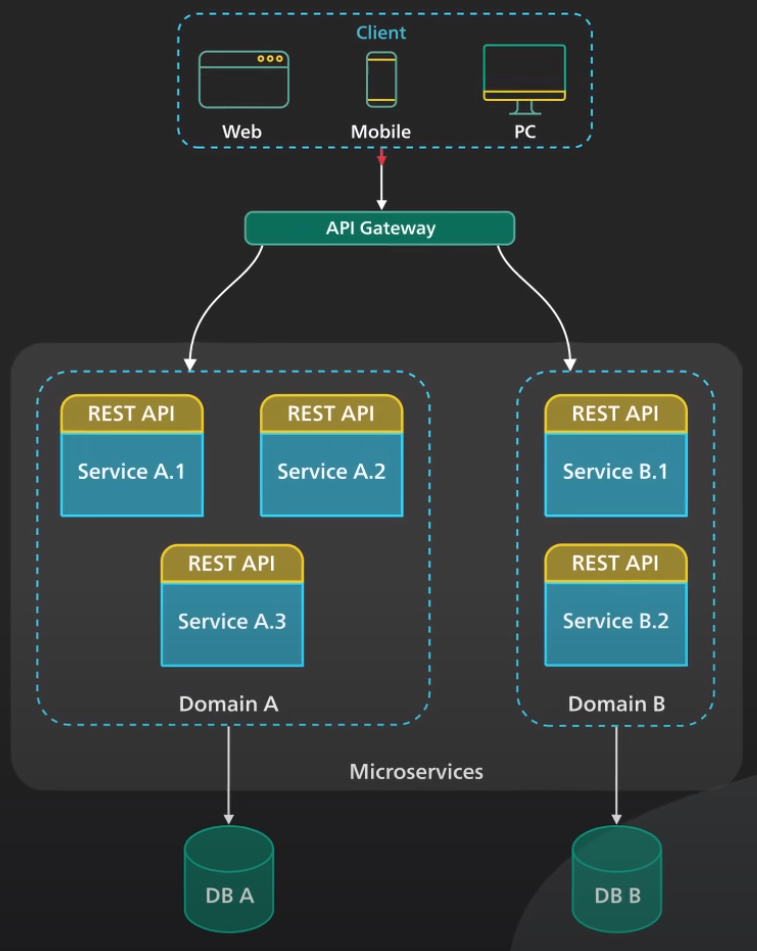
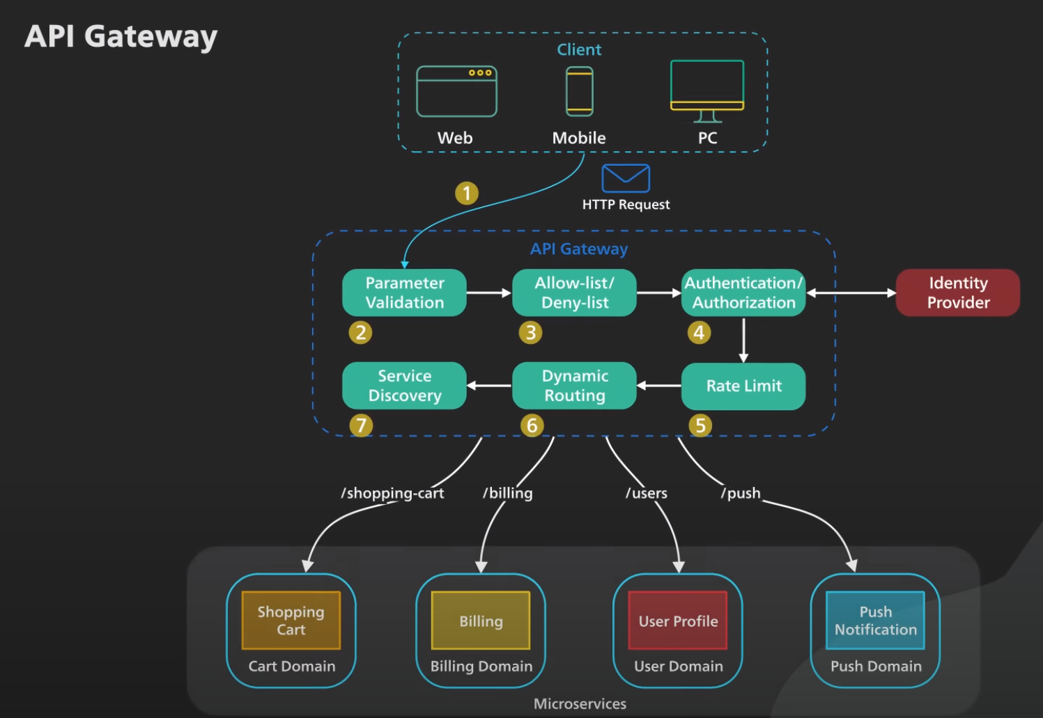
API Gateway
An API gateway is a single point of entry to the clients of an application, it sits between the clients and a collection of backend services for the application. An API gateway provides several important functions:
- Authentication and Security Policy Enforcements.
- Load Balancing and Circuit Breaking.
- Protocol Translation and Service Discovery.
- Monitoring, Logging, Analytics, and Billing.
- Caching.
Workflow
- The client sends a request to the API gateway. The request is typically a HTTP-based. It could be REST, GraphQL, or higher-level abstractions.
- The API gateway validates the HTTP request.
- The API gateway checks the caller’s IP address and other HTTP headers against its allow-list and deny-list. It could also perform basic rate limit checks against attributes such as IP address and HTTP headers. For example, it could reject requests from an IP address exceeding a certain rate.
- The API gateway passes the request to an identity provider for authentication and authorization. The API gateway gets back from the provider with a scope of what the request is allowed to do.
- A higher level rate-limit check is applied against the authenticated session. If it is over the lomit, the request is rejected at this point. 6-7. With the help of a service discovery component, the API gateway locates the appropriate backend service to handle the request by path matching.
- The API gateway transform the requests into the appropriate protocol and sends the transformed request to the backend service. A protocol can be gRPC. When the response comes back from the backend service, the API gateway transforms the response back to the public-facing protocol and returns the response to the client.
API gateway should be deployed to multiple regions to improve availability.
Proxy and Reverse Proxy
There are two common types of proxies are forward proxy and reverse proxy.
Forward Proxy
- Forward proxy is a server that sits between a group of client machine and the internet. When those clients make requests to websites on the internet, the forward proxy acts as a middle-man intercepts those requests and talks to the web servers on behalf of those client machines.
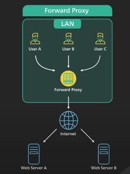
There are reasons why we use forward proxy:
- A forward proxy protects the client’s online identity, by using a forward proxy to connect to a website, the IP address of the client is hidden from the server. Only the IP address of the proxy is visible. It would be harder to trace back to the client
- A forward proxy can be used to bypass browsing restrictions. Institutions such as schools or government and big businesses use firewalls to restrict access to the internet. By connecting to a forward proxy outside the firewalls, the client machine can potentially get around these restrictions. This does not always work as the firewall can block the connection to the proxy.
- A forward proxy can be used to block a certain content by applying filters.
Reversed Proxy
- Reverse proxy sits between the internet and the web servers. It intercepts the requests from clients and talks to the web server on behalf of the clients.
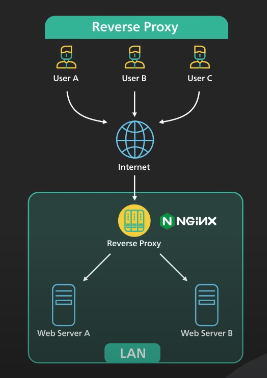
There are reasons why we use reversed proxy:
- A reversed proxy can be used to protects a website. The website’s IP addresses are hidden behaind the reversed proxy and are not revealed to the clients. This makes it much harder to target a DDoS attack against a website.
- A reversed proxy is used for load balancing. A popular website handling millions of users everyday is unlikely to be able to handle the traffic with a single server. A reversed proxy can balance a large amount of incoming requests by distributing the traffic to a large pool of web servers, and effectively preventing any single one of them to becoming overloaded. Services like Cloudflare put reverse proxy servers in hundreds of locations all around the world. This puts the reversed proxy closer to the users and at the same time provides a large amount of processing capacity.
- A reversed proxy can cache a static content.
- A reversed proxy can handle SSL encryption. SSL handshake is computationally expensive. A reversed proxy can free up the origin servers from these expensive operations. Instead of handling SSL for all clients, a website only needs to handle SSL handshake from a small number of reverse proxies.
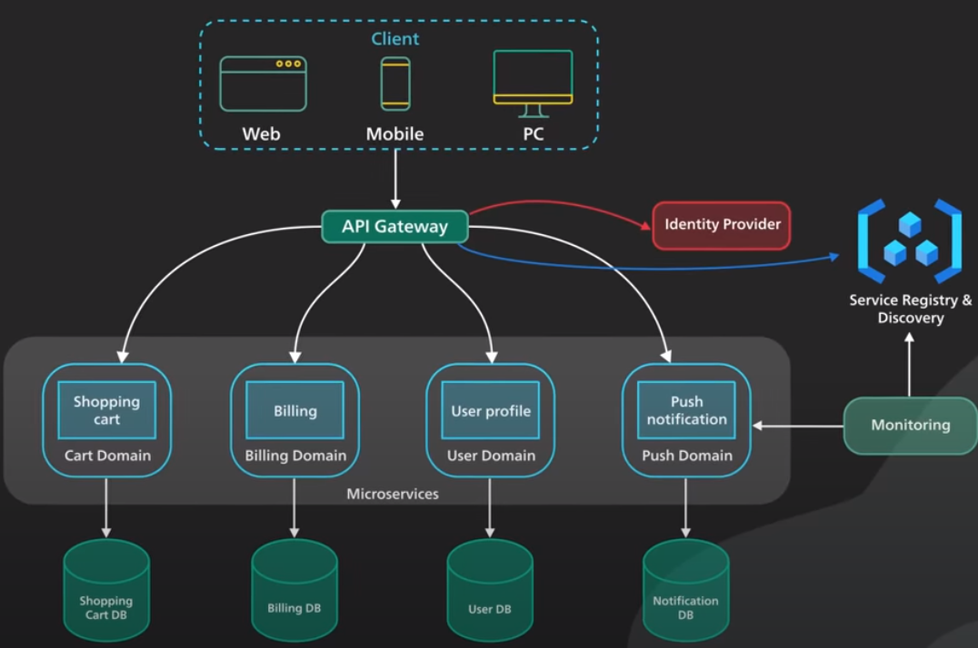
Microservices
Microservices architecture enables large teams to build scalable applications that are composed of many loosely coupled services. Each services handle a dedicated function inside a large-scale application. These functional areas are called domains.
Microservices communicate with each other via well-defined interfaces with small surface areas. The small surface areas limit the blast radius of failures and defects. It makes each service easier to reason about in the context of the entire applications.
Microservices talk to one another over a combination of remote procedure calls (RPC), event-streaming, or message brokers.
- RPC provides faster response, but the blast radius or the impact to other microservices would be larger when the services was to go down.
- Event-streaming provides better isolation between services but they take longer to process
Microservices can be independently deployed. Since each service is small, easier to reason about, and has a small blast radius, this gives the operators peace of mind and confidence to deploy often.
Microservices provide more flexibility to scale up individual microservices independently. The operational flexibilty is invaluable.
Well-architected microservices practice strong information hiding. This means breaking up a monolithic database into its logical components and keeping each logical component well hidden inside its corresponding microservice. The big drawback of microservices is the breaking up of database. By breaking up a database into separate logic units, the database can no longer maintain foreign keuy relationships and enforce referential integrity between these units. The burden of maintaining data integrity is now moved into the application layer
Other requirements needed for a successful microservices architecture:
- A key component is an API gateway. API gateway handles incoming requests and routes them to the relevant microservices. The API gateway relies on an identity provider service to handle the authentication and put authorization of each request coming through the API gateway. To locate the service to route an incoming request to, the API gateway consults a service registry and discovery service. Microservices register with this service registry and discover the location of other microservices through the discovery service.
- Monitoring, alering, DevOps toolings for deployment and troubleshooting are needed.
When to use Microservices
Microserivces cost money to build and operate. It really only make sense for large teams. This enables team independence. Each domain or function can be independently maintained by a dedicated team. In a well-designed microservices architecture, these independent teams can move faster, and blast rarius of failures is well-contained. Each service could be independently designed, deployed, and scaled.
Microservices are not a good fit for startups.
Kafka
In what senses that Kafka is fast? Latency? Throughput? Fast compared to what?
Kafka is optimized for high throughput. It is designed to move a large number of records in a short amountt of time. Think of it as a very large pipe moving liquid: The bigger the diameter of the pipe, the larger the volumn of liquid that can move through it.
So “Kafka is fast” indicates Kafka’s ability to move a lot of data efficiently. What are some of the design decisions that help Kafka move a lot of data quickly? There are several reasons but the top 2 are: Sequential I/O and Efficiency
Sequential I/O
Kafka relies on Sequential I/O. There’s a misconception that disk access is slow compared to memory access, but this largely depends on data access patterns. There are two types of access patterns: Random and Sequential. For hard drives, it takes time to physically move the arm to different location on the magnetic disks. This is what makes random access slow. For sequential access, since the arm doesn’t need to jump around, it is much faster to read and write blocks of data one after the other. Kafka takes advantage of this by using an append-only log as its primary data structure. An append-only log adds new data to the end of the file. This access pattern is sequential.
Specifically, on modern hardward with an array of these hard disks, sequential writes reach hundreds of megabytes per second, while random writes are measured in hundreds of kilobyte per second. Sequential access is a several order of magnitude faster.
Using hard disks has its cost advantage: Compared to SSD, hard disks come at one-third of the price but with about 3 times the capacity. Giving Kafka a large pool of cheap disk space without any performance penalty means that Kafka can cost effectively retain messages for a long period of time, a feature that was uncommon to messaging systems before Kafka.
Efficiency
Kafka is known for focusing on efficiency. Kafka moves a lot of data from network to disk, and from disk to network. It is critically important to eliminate excess copy when moving pages and pages of ata between the disk and the network. This is where zero copy principle comes into the picture. Modern unix operating systems are higly optimized to transfer data from disk to network without copying data excessively.
Let’s first look on how Kafka sends a page of data on disk to the consumer when zero copy is not used at all.
- First, the data is loaded from disk to the OS cache.
- Second, the data is copied from the OS cache into the Kafka application.
- Third, the data is copied from Kafka to the socket buffer.
- Fourth, the data is copied from the socket buffer to the network interface card buffer.
- Finally, the data is sent over the network to the consumer.
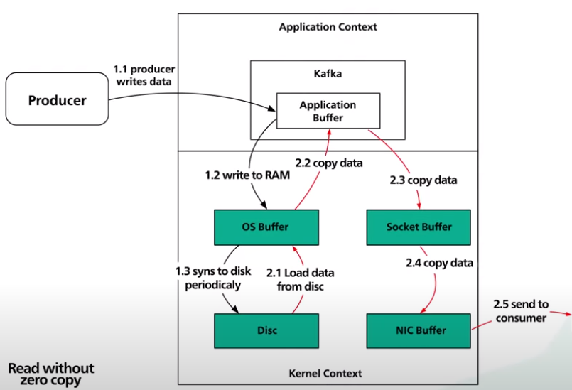
These five steps are clearly inefficient since there are 4 copies and 2 system calls.
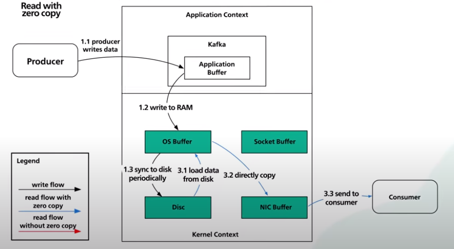
Now, let’s take a look at zero copy:
- First, the data is loaded from disk to the OS cache. With zero copy, the Kafka application uses a system call called
sendfile()to tell the operating system to directly copy the data from the OS cache to the network interface card buffer. In this optimized path, the only copy is from the OS cache into the network card buffer. With a modern network card, this copying is done with direct memory access (DMA). When DMA is used, the CPU is not involved, making it even more efficient.
Store & Validate Passwords To Database
It’s essential to store passwords in a way that keeps an attacker from getting them even if the database is compromised.
What is not to do: Do not store password in plaintext. ANyone with internal access to the database can see them. If the database is compromised, an attacker could easily get all the passwords
The Open Web Application Security Project (OWASP) provided some guidelines on how to store passwords:
- First, use a modern hashing algorithm. Hashing is a one-way function, it is impossivle to decrypt a hash to obtain the original value. If an attacker obtained the hashed password, they can’t just enter it into the application to gain access. It’s important to use a modern hashing function designed to securely store passwords. These functions are slow that use more resources to compute. This makes brute force attacks unattractive. There are some legacy hashing functions like MD5 and SHA-1 are fast. They are less secure and should not be used.
- Second, salt the passwords, a salt is a unique randomly generated string that is added to each password as
a part of a hashing process. Why do we need to salt the password at all? Storing a password as a one-way hash is a step in the right direction, but not sufficient. An attacker can defeat one-way hashes with pre-computation attacks. Some common attacks are rainbows tables and database-based lookups. With these techniques, a hacker could crack a password in seconds. By adding a salt that is unique to each password to the hashing process, it ensures that the hash is unique to each password. This simple technique makes pre-computation attacks unattractive.
Salt & Hash
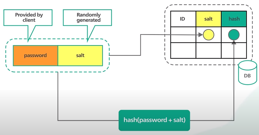
Let’s look to see how we store the password:
- First, combine the password provided by the user with the randomly generated salt.
- Then, we compute the hash of this combination using an appropriate hashing function.
- The hash is stored in the database along with the salt. The salt is used to generate unique hash. It’s not a secret and can be stored safely as plaintext in the database.
Let’s look to see how to validate the password:
- When a user logs in, we fetch the salt for the user from the database.
- We then append the salt to the password provided by the user and hash it.
- We compare this computed hash against the hash stored in the database. If they are the same, the password is valid.
Bare Metal, Virtual Machines, & Containers
When building a system, which one do we use?
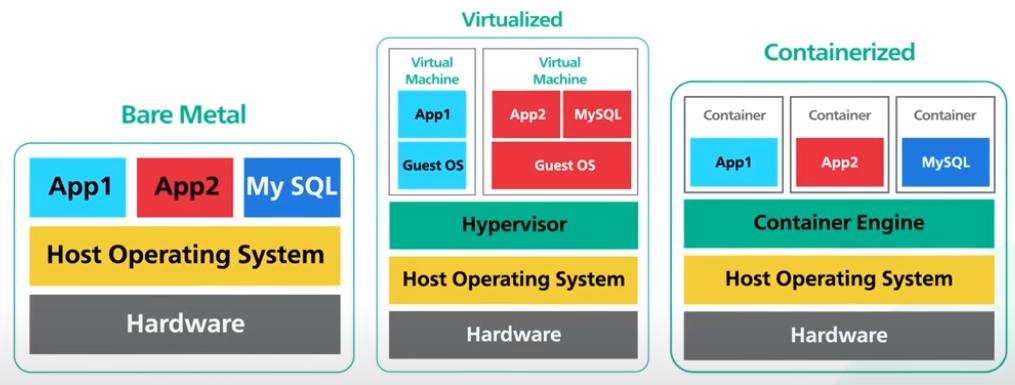
Bare Metal
A bare metal server is a physical computer that is a single tenant only. Bare metal gives us complete control over the hardware resources and the software stack to run. For software applications that require the absolute highest performance from the hardware, bare metal could be a good way to go.
Advantages - Bare metal servers are physically isolated, which provides 2 benefits:
- It is not affected by the noisy neighbor problem. This problem occures when one tenant’s performance is impacted because of the activities of another tenant sharing the same hardware.
- Isolation provides the highest level of security. For example, it is not affected by side-channel attacks. These attacks take advantage of the design flaws in modern microprocessors to allow a malicious tenant to steal secrets from its neighbors.
Disadvantages:
- Expensive.
- Hard to manage.
- Hard to scale.
- Take time to install.
- Take a competent team to manage.
Virtual Machines
A virtual machine is the emulation of a physical computer, this is called virtualization. Many virtual machines can run on a single piece of bare metal hardware. On top of the bare metal hardware is the host operating system. Running on top of the host operating system is a hypervisor (virtual machine monitor). The hypervisor manages virtual machine. It creates an abstraction layer over the hardware so that multiple operation systems can run alongside each other.
Each virtual machine has its own guest operating system. On top of each guest operating system runs the application for a tenant. Note that Bare Metal Hypervisor != Bare Metal Hardware.
A bare metal hypervisor controls the hardware directly without relying on the host operating system. This gives the hypervisor full control over the hardware and provides higher performance. However, hardware that supports the bare metal hypervisor is more expensive.
Advantages:
- Cheaper to run.
- Share the same hardware.
- Resources utilization.
- Easier to scale (vertically or horizontally).
Disadvantages:
- Virtual machine could be vulnerable to the noisy neighbor problem described earlier. If our application co-locates with a resource hog of a neighbor, our own application performance could suffer.
- Virtual machine running on the same bare metal hardware share the same physical CPU cores. They are vulnerable to attacks that aim at design flaws in modern processors. Side-channel attacks like Meltdown and Spectre are well-known examples.
Containers
A container is a lightweight and standalone package of an application with all its dependencies like libraries, frameworks, and runtime. Containerization is considered to be a lightweight version of virtualization.
For container, we got the hardware, host OS, container engine, and severals running containers. Each container is its own application environment. The container engine provides even faster resource provisioning. All the resources needed to run the application are packaged together, so that the applications can run anywhere.
Advantages:
- Containers are scalable and portable.
- A bare metal can store significantly more containers than virtual machines.
- Since each container runs as a native process of the host OS, they are much faster to start too.
Disadvantages:
- Less secure. They share the same underlying OS amd the isolation relies on the OS-level primitives. This means containers are exposed to a wider class of security vulnerabilities at the OS level.
It is possible to run containers in virtual machine for better security by reducing the possible attack surfaces. This is the trade-off between flexibility and security.
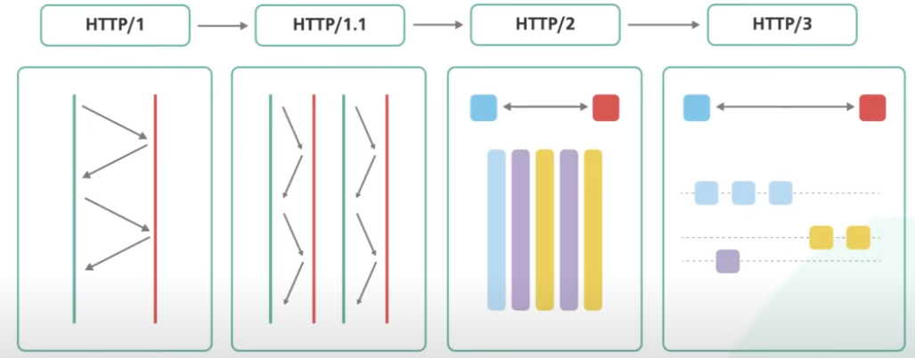
HTTP/1, HTTP/1.1, HTTP/2, & HTTP/3
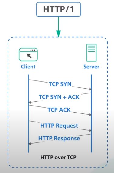
HTTP/1
HTTP/1 is built on top of TCP. Every request to the same server requires a separate TCP connection.
HTTP/1.1
HTTP/1.1 introduces a keep-alive mechanism so a connection could be reused for more than a single request. The persistent connections reduce request latency because the cleint does not need to initiate expensive TCP three-way handshake for every request.

HTTP/1.1 also added HTTP pipelining. In theory, this allows the client to send multiple requests before waiting for each response. The response must be received in the same order as to requests. It was tricky to implement correctly and many proxuy servers in between did not handle pipelining properly. Its support was eventually removed from many web browsers.

HTTP/1.1 with pipelining also suffers from an issue called head of line blocking. Without align blocking, subsequent requests on the same connection must wait for the previous requests to complete. If a request is blocked for any reason like packet loss, all subsequent requests on the same connection are also impacted
HTTP/2
HTTP/2 introduces HTTP streams, where multiple streams of requests could be sent to the same server on a single TCP connection. Unlike HTTP/1.1 with pipelining, each stream is independent of each other, and it does not need to be sent or received in order.
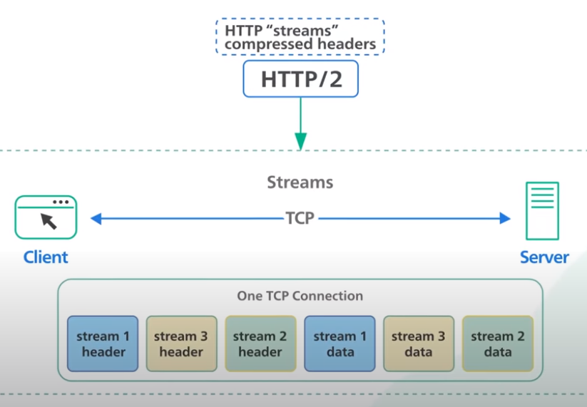
HTTP/2 solves the headline blocking issue at the application layer but the issue still exists in the transport layer with TCP. Also note that HTTP/2 introduced a push capability to allow servers to send updates to the clients whenever new data is available without requiring a client to poll.
HTTP/3
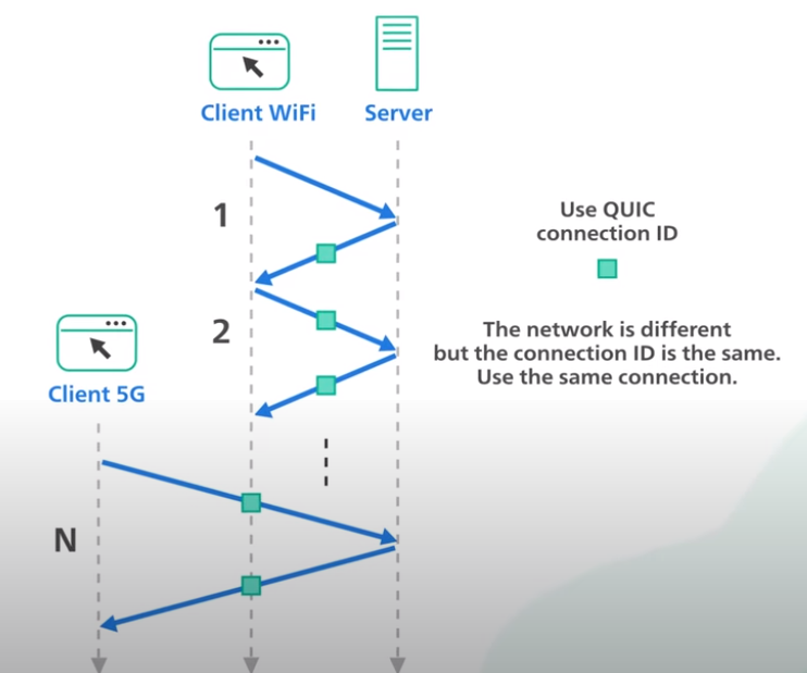
HTTP/3 uses the new protocol called QUIC instead of TCP as the underlying transport protocol. QUIC is based on UDP. It introduces streams as the first-class citizen at the transport layer. QUIC streams share the same quick connection, so no additional handshakes are required to create new ones.

QUIC streams are delivered independently. In most cases, packet loss affect one stream doesn’t afect others. This is how QUIC eliminates the head of line blocking at the transport layer.
QUIC is designed for mobile heavy internet usage. People carrying smartphones constantly switch from one network to another as they move about their day. With TCP, the handoff of one connection from one network to another is sluggish. QUIC implements a concept called connection ID, which allows connections to move between IP addresses and network interfaces quickly and reliably.
Citation
Cited as:
System Design Fundamentals Mega-Blog https://mnguyen0226.github.io/posts/system_design_concepts/post/
Or
@article{nguyen2023sdmega,
  title   = "System Design Concepts Mega-Blog",
  author  = "Nguyen, Minh",
  journal = "mnguyen0226.github.io",
  year    = "2023",
  month   = "January",
  url     = "https://mnguyen0226.github.io/posts/system_design_concepts/post/"
}
References
[1] A. Xu, System Design Interview - An Insider’s Guide. Independently Published, 2020.
[2] ByteByteGo, “10+ Key Memory & Storage Systems: Crash Course System Design #5,” YouTube. Mar. 28, 2023. Accessed: Oct. 25, 2023. [YouTube Video]. Available: https://www.youtube.com/watch?v=lX4CrbXMsNQ&list=PLCRMIe5FDPsd0gVs500xeOewfySTsmEjf
[3] ByteByteGo, “Latency Numbers Programmer Should Know: Crash Course System Design #1,” YouTube. Oct. 04, 2022. Accessed: Oct. 31, 2023. [YouTube Video]. Available: https://www.youtube.com/watch?v=FqR5vESuKe0&list=PLCRMIe5FDPsd0gVs500xeOewfySTsmEjf&index=3
[4] ByteByteGo, “What Is REST API? Examples And How To Use It: Crash Course System Design #3,” YouTube. Aug. 24, 2022. Accessed: Oct. 31, 2023. [YouTube Video]. Available: https://www.youtube.com/watch?v=-mN3VyJuCjM&list=PLCRMIe5FDPsd0gVs500xeOewfySTsmEjf&index=4
[5] ByteByteGo, “10 Key Data Structures We Use Every Day,” YouTube. May 01, 2023. Accessed: Oct. 31, 2023. [YouTube Video]. Available: https://www.youtube.com/watch?v=ouipSd_5ivQ&list=PLCRMIe5FDPsd0gVs500xeOewfySTsmEjf&index=5
[6] ByteByteGo, “Cache Systems Every Developer Should Know,” YouTube. Apr. 04, 2023. Accessed: Oct. 31, 2023. [YouTube Video]. Available: https://www.youtube.com/watch?v=dGAgxozNWFE&list=PLCRMIe5FDPsd0gVs500xeOewfySTsmEjf&index=6
[7] ByteByteGo, “Top 5 Redis Use Cases,” YouTube. Feb. 16, 2023. Accessed: Oct. 31, 2023. [YouTube Video]. Available: https://www.youtube.com/watch?v=a4yX7RUgTxI&list=PLCRMIe5FDPsd0gVs500xeOewfySTsmEjf&index=10
[8] ByteByteGo, “CI/CD In 5 Minutes | Is It Worth The Hassle: Crash Course System Design #2,” YouTube. Jan. 18, 2023. Accessed: Nov. 01, 2023. [YouTube Video]. Available: https://www.youtube.com/watch?v=42UP1fxi2SY&list=PLCRMIe5FDPsd0gVs500xeOewfySTsmEjf&index=11
[9] ByteByteGo, “Kubernetes Explained in 6 Minutes | k8s Architecture,” YouTube. Jan. 11, 2023. Accessed: Nov. 01, 2023. [YouTube Video]. Available: https://www.youtube.com/watch?v=TlHvYWVUZyc&list=PLCRMIe5FDPsd0gVs500xeOewfySTsmEjf&index=12
[10] ByteByteGo, “CAP Theorem Simplified,” YouTube. Jan. 03, 2023. Accessed: Nov. 01, 2023. [YouTube Video]. Available: https://www.youtube.com/watch?v=BHqjEjzAicA&list=PLCRMIe5FDPsd0gVs500xeOewfySTsmEjf&index=13
[11] ByteByteGo, “What is OSI Model | Real World Examples,” YouTube. Dec. 23, 2022. Accessed: Nov. 02, 2023. [YouTube Video]. Available: https://www.youtube.com/watch?v=0y6FtKsg6J4&list=PLCRMIe5FDPsd0gVs500xeOewfySTsmEjf&index=14
[12] ByteByteGo, “What Is A CDN? How Does It Work?,” YouTube. Nov. 24, 2022. Accessed: Nov. 02, 2023. [YouTube Video]. Available: https://www.youtube.com/watch?v=RI9np1LWzqw&list=PLCRMIe5FDPsd0gVs500xeOewfySTsmEjf&index=15
[13] ByteByteGo, “What is RPC? gRPC Introduction.,” YouTube. Dec. 01, 2022. Accessed: Nov. 04, 2023. [YouTube Video]. Available: https://www.youtube.com/watch?v=gnchfOojMk4&list=PLCRMIe5FDPsd0gVs500xeOewfySTsmEjf&index=19&ab_channel=ByteByteGo
[14] ByteByteGo, “What Is GraphQL? REST vs. GraphQL,” YouTube. Nov. 10, 2022. Accessed: Nov. 04, 2023. [YouTube Video]. Available: https://www.youtube.com/watch?v=yWzKJPw_VzM&list=PLCRMIe5FDPsd0gVs500xeOewfySTsmEjf&index=17&ab_channel=ByteByteGo
[15] ByteByteGo, “What is API Gateway?,” YouTube. Nov. 01, 2022. Accessed: Nov. 07, 2023. [YouTube Video]. Available: https://www.youtube.com/watch?v=6ULyxuHKxg8&list=PLCRMIe5FDPsd0gVs500xeOewfySTsmEjf&index=20
[16] ByteByteGo, “Proxy vs Reverse Proxy (Real-world Examples),” YouTube. Oct. 25, 2022. Accessed: Nov. 07, 2023. [YouTube Video]. Available: https://www.youtube.com/watch?v=4NB0NDtOwIQ&list=PLCRMIe5FDPsd0gVs500xeOewfySTsmEjf&index=19
[17] ByteByteGo, “What Are Microservices Really All About? (And When Not To Use It),” YouTube. Oct. 11, 2022. Accessed: Nov. 07, 2023. [YouTube Video]. Available: https://www.youtube.com/watch?v=lTAcCNbJ7KE&list=PLCRMIe5FDPsd0gVs500xeOewfySTsmEjf&index=20
[18] ByteByteGo, “System Design: Why is Kafka fast?,” YouTube. Jun. 29, 2022. Accessed: Nov. 07, 2023. [YouTube Video]. Available: https://www.youtube.com/watch?v=UNUz1-msbOM&list=PLCRMIe5FDPsd0gVs500xeOewfySTsmEjf&index=21
[19] ByteByteGo, “System Design: How to store passwords in the database?,” YouTube. Jul. 06, 2022. Accessed: Nov. 08, 2023. [YouTube Video]. Available: https://www.youtube.com/watch?v=zt8Cocdy15c&list=PLCRMIe5FDPsd0gVs500xeOewfySTsmEjf&index=22
[20] ByteByteGo, “Big Misconceptions about Bare Metal, Virtual Machines, and Containers,” YouTube. Jul. 14, 2022. Accessed: Nov. 08, 2023. [YouTube Video]. Available: https://www.youtube.com/watch?v=Jz8Gs4UHTO8&list=PLCRMIe5FDPsd0gVs500xeOewfySTsmEjf&index=23
[21] ByteByteGo, “HTTP/1 to HTTP/2 to HTTP/3,” YouTube. Aug. 17, 2022. Accessed: Nov. 08, 2023. [YouTube Video]. Available: https://www.youtube.com/watch?v=a-sBfyiXysI&list=PLCRMIe5FDPsd0gVs500xeOewfySTsmEjf&index=24
